
Skills: SE & optical microscopy, EDS, XRF, CT, Metallurgy/Microstructural analysis, Instron Mechanical Testing
I led a research project analyzing sustained load cracking (SLC) in AA6351-T6 aluminum gas cylinders, with the goal of improving material performance and safety standards for high-pressure applications.
Read the Full Paper:
Roos, C., Stolk, J.D., Brinkmann, W., Vo, K., Skelly, W., 2025. The causes of sustained load cracking in aluminum 6351-T6 gas cylinders. Materials & Design 258, 114538. https://doi.org/10.1016/j.matdes.2025.114538
This case study combined comprehensive material characterization, microstructural and property analysis, a review of prior research, and a critical assessment of testing standards. It includes recommendations for failure prevention, risk assessment, and safety improvements. Computed tomography (CT) scanning, optical microscopy, scanning electron microscopy (SEM), energy dispersive X-ray spectroscopy (EDS), and X-ray fluorescence (XRF) were used to analyze a large crack in a working gas cylinder and investigate the causes of SLC. This page provides a brief summary; please refer to the manuscript for full details.

Introduction:
Gas cylinders made of the Al-Mg-Si alloy AA6351 have shown susceptibility to sustained load cracking (SLC) in the neck and shoulder region, which has led to catastrophic failures.
These cylinders are widely used in self-contained underwater breathing apparatus (SCUBA), self-contained breathing apparatus (SCBA), and medical (oxygen) services and are typically stored pressurized to prevent moisture and contaminants from entering the cylinder or valve. SLC is a metallurgical phenomenon where cracks develop in materials under a constant load over time.
Previous studies examined heavy metal embrittlement and its potential impact on SLC in aluminum alloys. This study analyzes the microstructure of AA6351-T6 cylinders, characterizes SLC in a damaged but still-operational cylinder, and investigates the effects of alloy processing and lead-induced intergranular fracture under sustained load and slow strain rate conditions. It also discusses potential improvements to inspection and testing protocols.
Non-Destructive Testing:
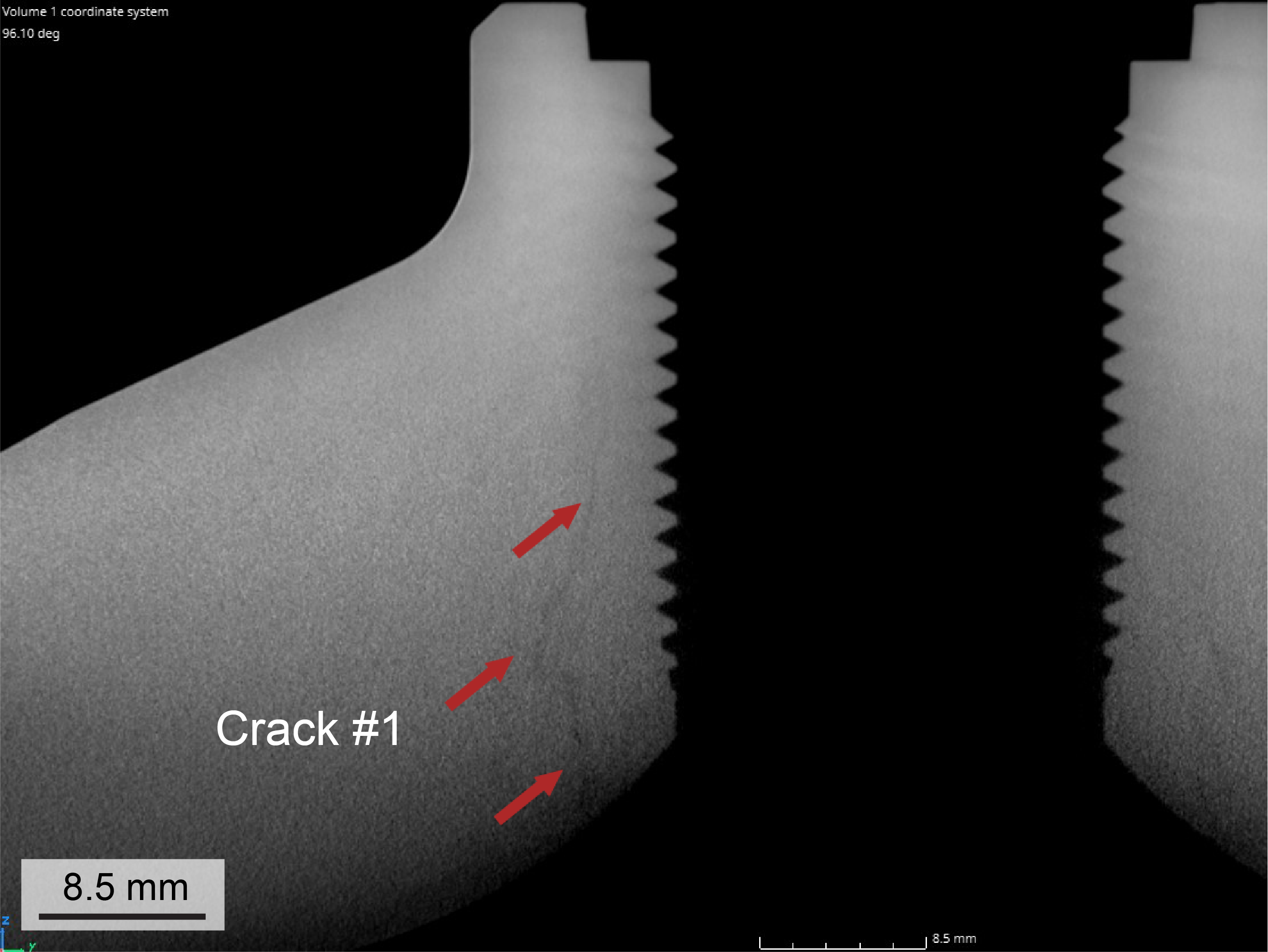
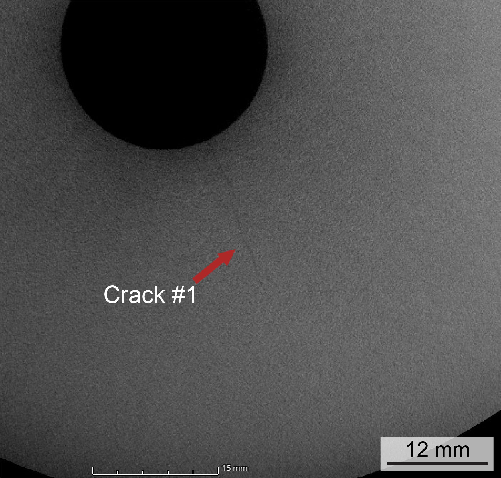
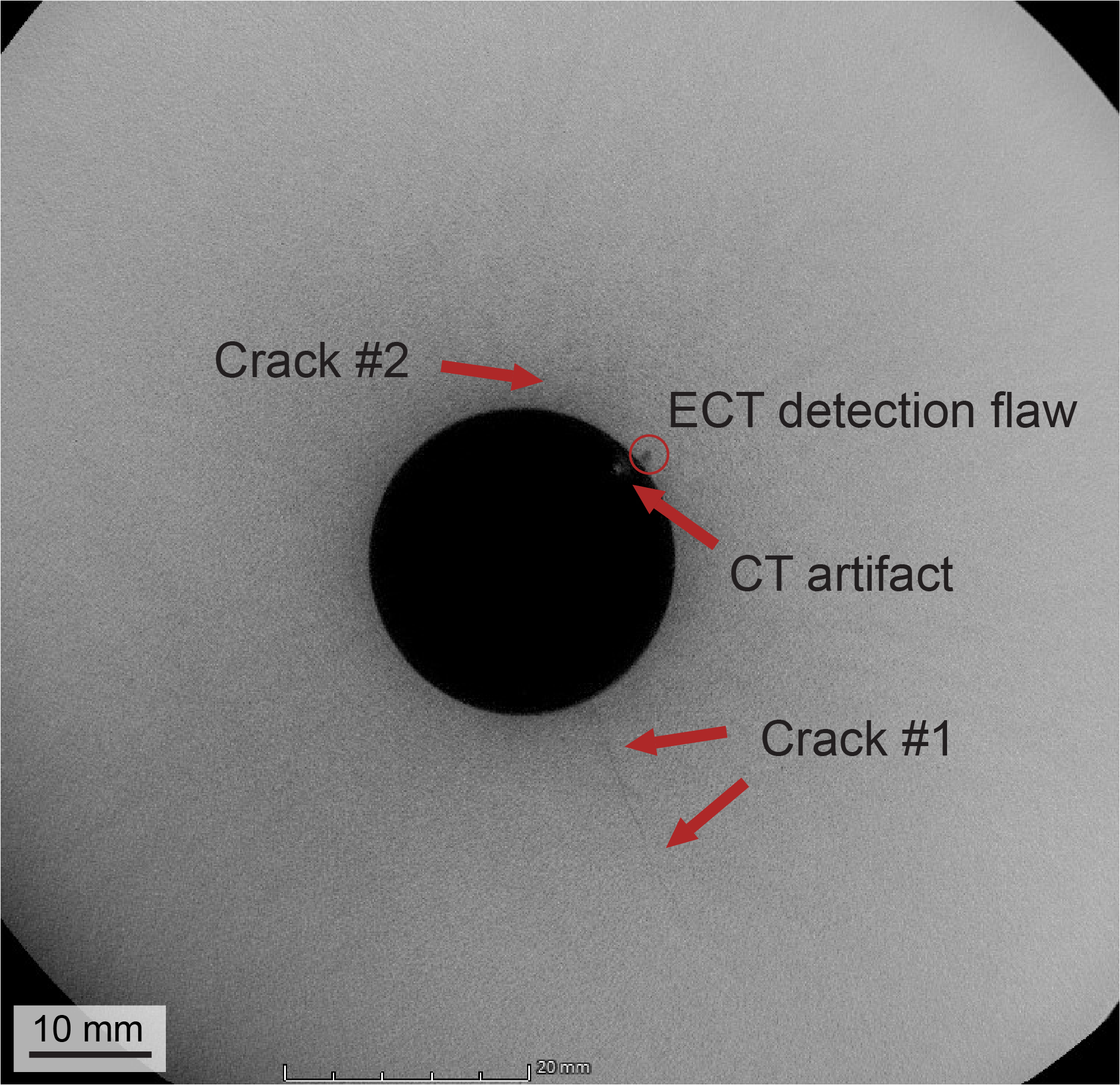
Eddy current testing (ECT) was performed on the cylinder, which detected a singular flaw (of unknown type/dimensions). I then examined the cylinder using computed tomography (CT) to locate and characterize any potential flaws. In examining the CT data I discovered the ECT had identified a single void of approximately 1.56 mm in diameter while full CT data revealed numerous critical cracks that had gone undetected by ECT. Using the CT data I visually reconstructed the largest crack dimensions in CAD as can be noted in the figure below. Based on the CT results, I sectioned the cylinder to visualize the largest radial neck crack, enabling detailed microstructural analysis.
CT scan images of the examined crack
Crack location in reference to ECT detected flaw

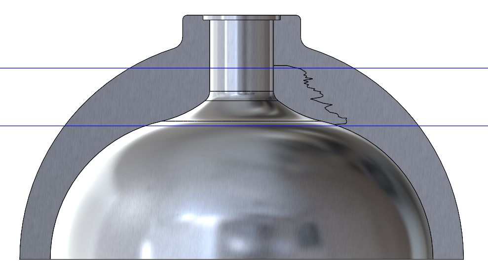
CAD of the ROI of the cylinder with the examined crack dimensions visualized (from CT data). Blue lines denote the location of the sections taken for metallographic analysis, which are 22 mm and 46 mm from the top of the cylinder.
Metallographic Sample Preparation:
I sectioned three samples from the radial crack for detailed analysis. Two were ground to 800-grit SiC paper and polished to 0.05 µm colloidal silica: one was left as-polished for EDS analysis, while the other was micro-etched with Tucker's reagent for metallographic examination. The third, unpolished sample was fractured in tension on an Instron mechanical tester for fractographic analysis. Away from the crack, I prepared a vertical cross-section of the cylinder neck to analyze grain size, following the same polishing and etching procedure. All samples were imaged using optical microscopy and SEM, and I took linear intercept grain measurements across three planes to characterize the microstructure.
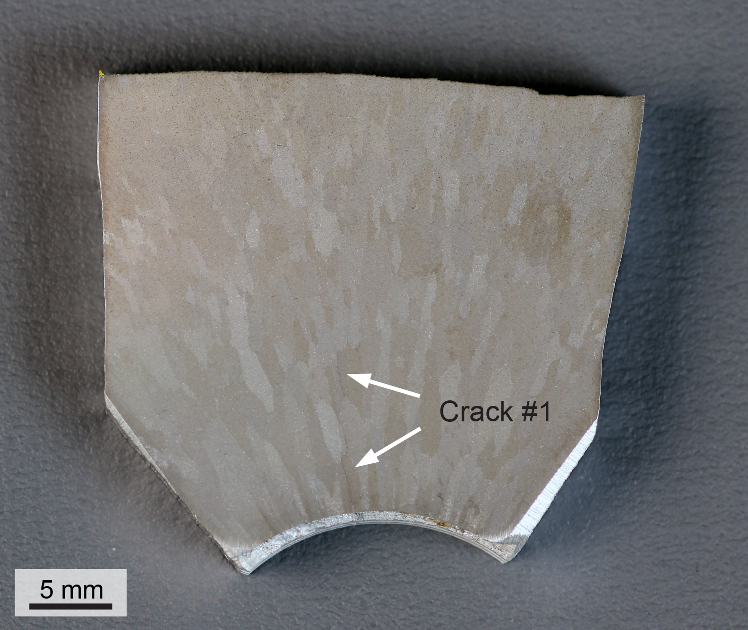
Micro etched neck cross section revealing enlarged grains and the examined crack (annotated) propagating along the grain boundaries. Tucker’s reagent etch.
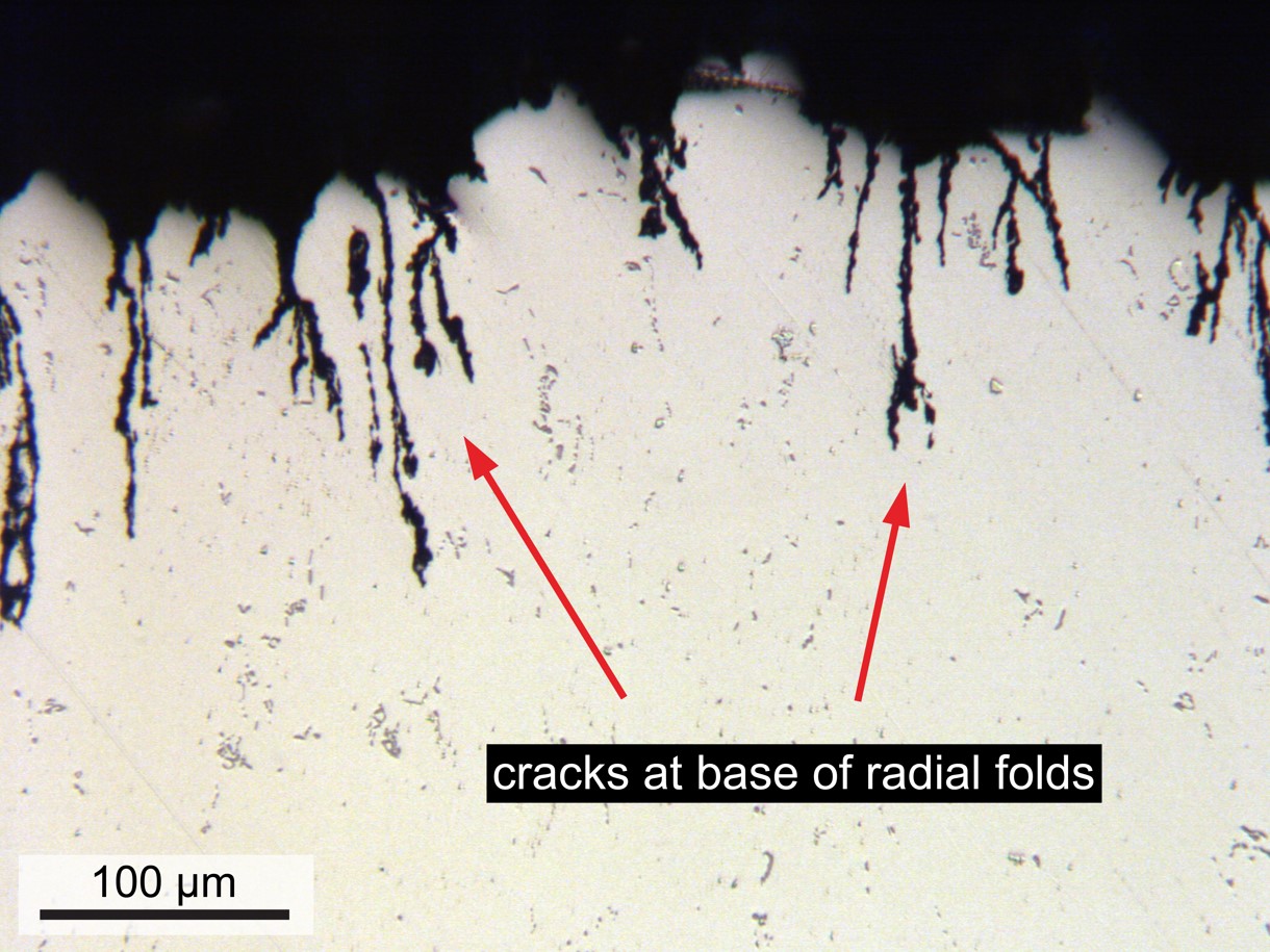
Optical micrograph showing sub-critical cracks at the internal folds of the cylinder neck. As-polished.

Optical micrograph illustrating crack propagation along the grain boundaries. Tucker’s reagent etch.
Alloy Composition:
I performed X-ray fluorescence (XRF) analysis on the as-polished specimen to determine bulk alloy composition, confirming it matched the nominal AA6351 specification. The bulk lead content was measured at 17 ppm. Given the XRF results and previous literature I predicted lead embrittlement was a factor due to lead diffusing to the grain boundaries to relieve stresses at the crack tip. I thus performed EDS linescans, spot analyses, and compositional mapping which revealed higher lead concentrations along the crack compared to unfractured surfaces. I also observed elevated silicon content near the fracture surface, which appears to result from selective corrosive attack of the multiphase alloy at the exposed crack, with Si increasing closer to the crack opening.
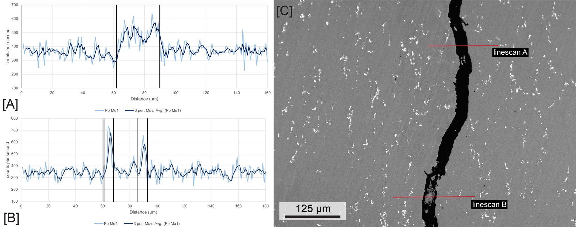
[A] EDS linescan of Pb content across a single crack for which the black lines denote the start and end of the crack; [B] EDS linescan of Pb content across a branched crack for which the vertical black lines denote the start and end of the branched crack. The section between the two cracks is the aluminum matrix phase; [C] associated SEM micrograph denoting linescan locations.

EDS compositional mapping of the Pb content across a cracked section of the as-polished sample: [A] map of the Pb content revealing Pb concentration in the crack and near the crack tip; [B] associated SEM micrograph.
Mechanical Properties:
I machined tensile specimens from the cylinder body following ASTM E8/E8M standards and performed Instron tensile tests to characterize the material. The results indicated lower tensile and yield strengths, but higher ductility, compared to nominal AA6351 specifications. I also measured Vickers microhardness in the neck and body, finding slightly higher hardness in the neck and significantly lower hardness in the body relative to the nominal alloy.
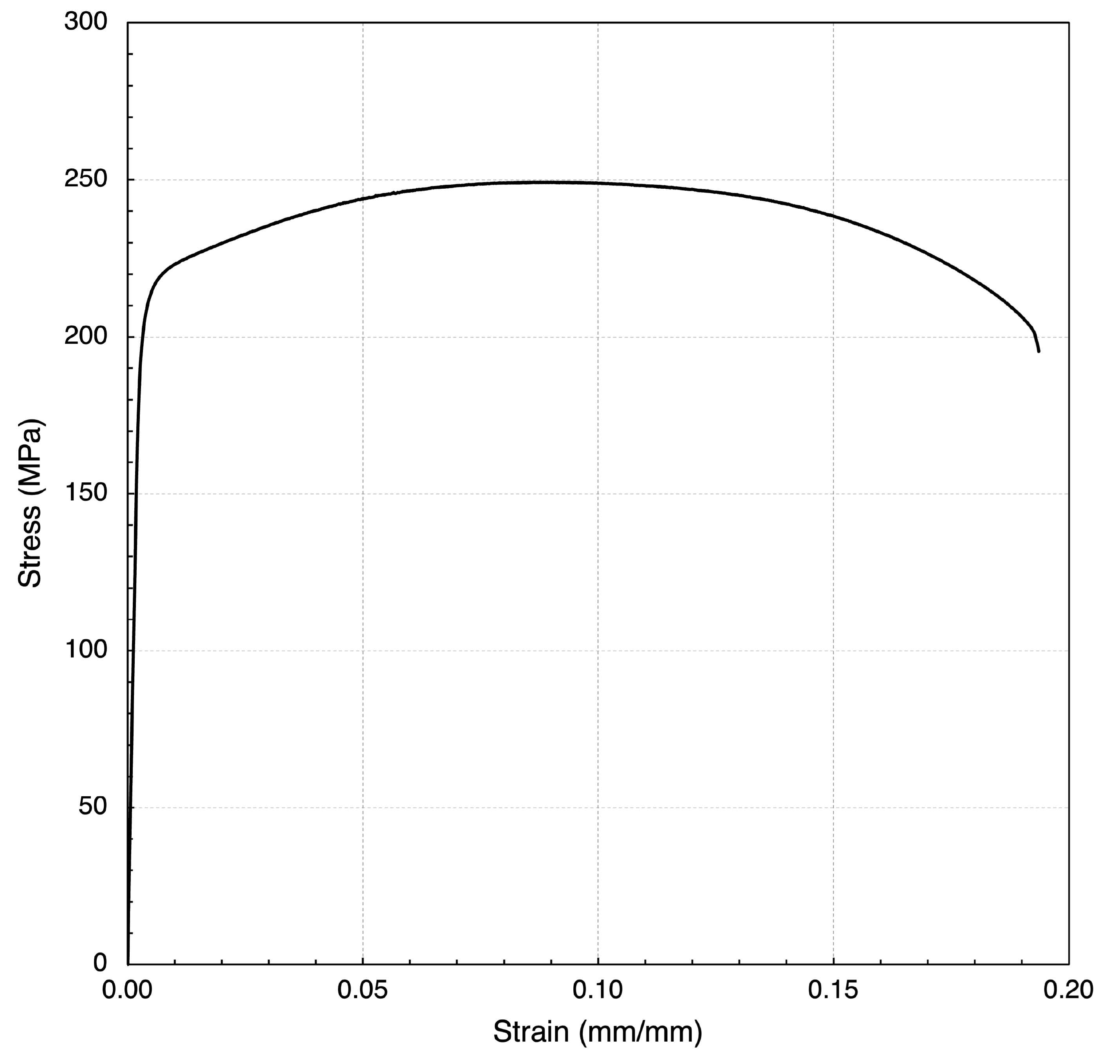
Stress–strain curve for the AA6351-T6 tensile specimen tested under uniaxial tension at a displacement rate of 2 mm/min (crosshead rate controlled) at room temperature.
Fractography:
I examined the fracture surfaces using SEM, EDS, XRF, and ED-XRF. ED-XRF analysis revealed higher lead content on the fracture surfaces compared to the as-polished specimens.
SEM inspection showed a thick oxide layer covering much of the fracture surface, likely from improper storage after the cylinder was condemned. In areas of bare metal, I observed primarily low-ductility intergranular fracture (LDIGF), consistent with prior research on the effects of lead in AA6351 sustained load cracking. Lead globules, appearing brighter in backscattered electron mode, were visible along the fracture surface, supporting the theory of lead diffusion to crack tips during fracture. Small regions of intergranular microvoid coalescence (IGMVC) were also present.
Analysis of a fast-fracture tensile specimen from the cylinder body revealed primarily transgranular microvoid coalescence (TGMVC), with localized regions of less ductile IGMVC.
SLC fracture surfaces with oxide visible as white (left) and gray (middle) discoloration. Light areas at the right edge are fast fracture from in-lab sample preparation.

SEM micrographs revealing: [A] LDIGF across most of the fracture surface with smaller IGMVC sections. The fracture surface oxide layer is visible on the right-hand side; [B] the low magnification outline of a large grain at the fracture surface; [C] the oxide layer covering most of the fracture surface; [D] a low magnification boundary between large grains (lower left), suggesting low ductility intergranular fracture (LDIGF).
Conclusions:
My analysis determined that manufacturing defects were the primary cause of failure in this cylinder. Radial cracks form at the base of interior neck folds during the hot forming process, which acts as a catalyst for critical crack growth. This process also induces extensive grain growth along the neck curvature and generates residual stresses from forming and age hardening, producing tensile stresses on the cylinder interior and compressive stresses on the exterior—conditions that help explain initial crack propagation.
Once initiated, crack growth is influenced by the cylinder’s stress profile under working load and the alloy microstructure, with additional contributions from residual stresses. Lower hoop stress at the working pressure and compressive residual stresses near the outer surface may explain why cracks do not propagate directly to the exterior. While manufacturing defects were the main driver of failure, other factors, such as lead-induced embrittlement, also contributed to premature cracking.

Cross section of an unfailed (exemplar) SCUBA cylinder neck manufactured from AA6351-T6 by Luxfer. Excessive grain growth is visible following the curvature of the neck. Tucker’s reagent etch.
Low magnification stereo microscope image of the cracked cylinder, showing cracks at the base of the neck’s radial deformation marks (folds) along the inside surface.
Future Work:
During this project, I identified several promising avenues for further research, some of which I have begun pursuing independently. Recognizing the use of these cylinders in firefighting applications, I initiated thermal cycling analysis to investigate its potential impact on age hardening. I am also quantifying the combined effects of residual stresses and working pressure on crack growth behavior. While prior literature has modeled residual stresses, it rarely incorporates internal pressure quantitatively. My simulations aim to address this gap by modeling both factors simultaneously, with the goal of better predicting crack growth shape and evolution.
This page provides a brief overview of the study. For full details, including additional recommendations for failure prevention and potential future work, please refer to the published manuscript linked below or contact me directly at croos@alumni.olin.edu.
